I was recently talking with my friend Josh about some of the subtleties of audio wiring, and decided to write yet another tome. Information on audio gear is available in a lot of places, in much more detail than even I attempt, but I thought a concise explanation based on my practical experiences might be useful.
This is specifically about analog audio cables. Digital audio is a whole nother, and more complicated, bag.
The key sections included are:
The cables I am describing here are used to transmit electrical signals from one device to another. Generally speaking, an analog cable carries one signal in one direction through its attached connectors. For reasons of safety and operational isolation, these cables are assumed to be insulated with a non-conductive outer layer of plastic or rubber. (The type of insulation is important for installations which are expected to adhere to certain safety codes.)
In addition to "cable ", there are several relevant terms that are used when connecting audio, such as wire and cord. Merriam Webster defines a cable as "an assembly of electrical conductors insulated from each other but laid up together (as by being twisted around a central core) ". MW also defines cord as "a small flexible insulated electrical cable having a plug at one or both ends used to connect a lamp or other appliance with a receptacle," and wire as "a line of wire for conducting electric current," a somewhat recursive definition that also references the definition of cord.
All three are commonly used, as in speaker wire, microphone cord, or guitar cable. Like most popular disciplines, there is no standardized nomenclature, allowing an entertaining freedom of use, and occasional confusion.
I like cable (the word as well as the concept).
The connectors are used to simplify the process of attaching cables to devices. Strictly speaking, cables are necessary, but connectors are not. For years I have used lamp cord (also called "zip cord") to connect an amplifier to a speaker. In the early days, I just stripped the insulation off the wire, wrapped the wire around a screw, and tightened the screw. Later I bought a crimping tool and a box of terminals, which simplified and strengthened the connection. There are still consumer audio speakers available which use a spring-loaded clip to capture the stripped wire. But nowadays all professional audio gear, and most high-grade consumer gear, uses connectors.
If you are tasked with connecting two devices, there are three main factors to consider when selecting a cable from a box, stack, pile, or web site:
The connectors on the device offer a hint as to what sort of cable you should select, but the answer is not always as simple as that. Just because a cable can be attached to a connector doesn't mean that particular cable is the best choice. In some cases, it might just provide a less-then-perfect solution, but in others, it might not even be usable. Probably the best bad example is using a 1/4"-to1/4" speaker cable to connect a guitar to an amplifier. It will fit, but the hum it introduces into the amplifier will make it unusable.
This summary attempts to make you wiser so you can avoid that kind of situation.
These are the most common types of cable used to connect analog audio equipment.
| Type | Description | Example | Notes |
|---|---|---|---|
| unshielded pair | two stranded conductors held side-by-side by their insulation | lamp cord, which is inexpensive and perfectly suitable for low-power speaker connections on consumer audio equipment | stranded wire is used for flexibility due to its general larger gauge (24 to 18 gauge is typical); this cable type is not at all resistant to electromagnetic interference; fortunately, that is not a problem for speaker wire |
| unshielded twisted pair | two insulated conducters twisted in a spiral | analog telephone signals are generally carried over unshielded twisted pair; in some cases the individually insulated individual wires are encased in another outer layer of protective insulation | telephone cables are usually 22 to 25 gauge solid; audio cables are usually stranded to allow flexibility and prevent breakage in use |
| shielded twisted pair | two insulated, stranded conducters twisted in a spiral, then covered with a metallic shield or either foil, or fine wire in a spiral or braided configuration | a typical balanced, low-impedance microphone cable | this cable has the highest resistance to electromagnetic interference of any of the common audio cables listed here |
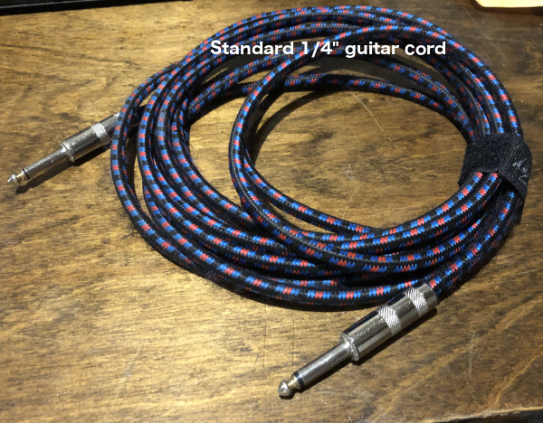
| single conductor with shield | a single insulated stranded conductor covered with a metallic shield or either foil, or fine wire in a spiral or braided configuration | a garden-variety guitar cord, or an inexpensive, high-impedance microphone cable | this popular cable has a medium resistance to electromagnetic interference compared to the other audio cables listed here |
| coaxial cable | an assembly consisted of a single solid conductor, a uniform layer of insulation of a specified thickness, covered with a metallic shield or either foil or braided wire | the cable connecting your set-top-box to a satellite dish or the cable television line passing through your neighborhood | a stiffer cable than the more flexible audio cables, for a more permanent installation; typically 75 ohm impedance; high resistance to electromagnetic interference, especially at higher video frequencies, since this cable is generally used for video; it is included here primarily for comparison |
These are the most common types of connectors used to connect analog audio equipment.
| Type | Description | Example | Image |
|---|---|---|---|
| RCA or phono | a coaxial, friction-held connector used for connecting devices which are typically not moved much, not subject to being stepped on or pulled out | often pre-manufactured into a cable assembly, but also available for manual assembly using a soldering iron | |
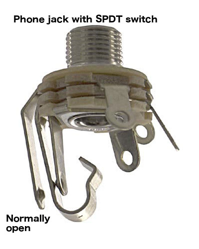
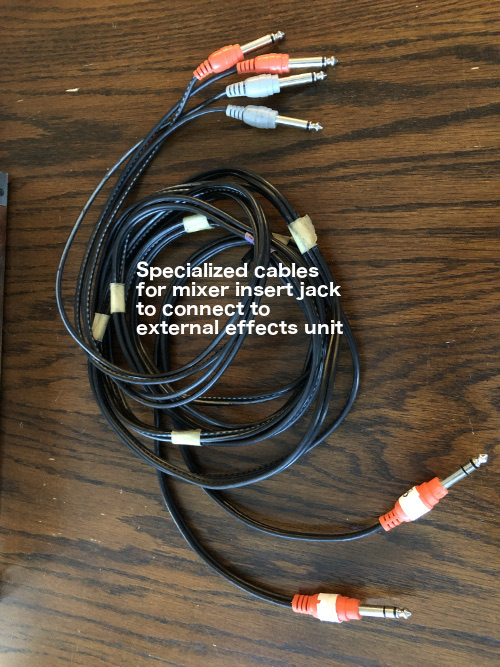
| phone (1/4") | a multi-purpose coaxial connector held in place by a spring mechanism in the jack; more appropriate for uses where the cable might be stepped on or pulled out; the conducting surfaces are exposed | Phone connector is available in multiple sizes and configurations; see specific versions, below. Note that the phone jack can include switching functionality which may be used to activate a battery-powered pre-amp in an acoustic guitar, or to re-route the signal in a mixer with the use of an insert cable (described below). | |
| phone (1/4"): tip/sleeve | two conductors; with shielded cable, the tip is normally the signal, and the sleeve is the shield and ground (see balanced circuits, below) | Used (and abused) for a wide variety of applications -- guitar cords, speaker cords, etc. depending what sort of cable they are attached to (unshielded pair or shielded twisted pair) | |
| phone (1/4"): tip/ring/sleeve | three conductors, generally used for special applications requiring shielded twisted pair | studio headphones, insert cables | |
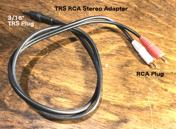
| phone (3mm or 1/8") | a small version of its 1/4" sibling; the plug and jack are smaller to take up less space, but are also easier to damage | many smart phones, tablets and computers use this size connector for stereo audio input and output; usually tip/ring/sleeve; note that smartphone earbuds often add an additional conductor and "sleeve" (TRSS?) which carries voice from the microphone back to the phone; some video camera connectors use a similar extra conductor and sleeve to transmit video; that is the mini version of the red-white-yellow RCA cable used by old video players and games | |
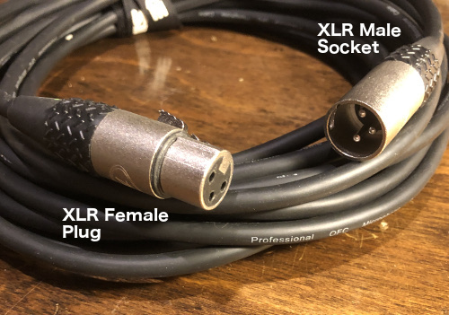
| XLR | a circular connector around 3/4" in diameter, usually with three pins to support a balanced, shielded twisted pair cable; designed to clip into place using a mechanical release button | Compared to 1/4" phone plug, very robust and not prone to damage or accidental disconnection; conducting surfaces are protected from physical contact and shorting | |
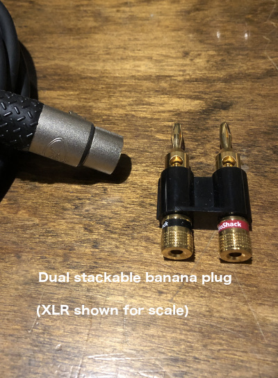
| Banana plug | a single conductor, high-current connector; generally used in pairs for speaker connections | available in a dual, stackable configuration to support multiple parallel connections (caution - too many parallel speaker connections will overload the amplifier | |
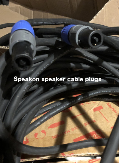
| Speaker Twist Connector (Neutrik Speakon) | a relatively new design which replaces 1/4" tip/sleeve connector for speaker applications; extremely durable, with a twist-locking mechanism to secure the cable to the speaker | Compared to 1/4" phone plug, very robust and not prone to damage or accidental disconnection; conducting surfaces are protected from physical contact and shorting | |
Different applications will require different combinations of connectors. For example:
Electrical interference at all frequencies surrounds us and our cables. The interference that we are concerned with ranges from 60 Hertz AC (which is easily audible in normal hearing range as a low hum, close to the next-to-lowest B on a normal piano), up to the frequencies used by radio stations (which has resulted in some embarrassing church service interruptions for chapels located near a local AM radio transmitter).
When these electromagnetic waves wash over a wire, they create a small, corresponding current in the wire. This current is added to the signal which is being transmitted through the wire, and is eventually amplified, creating audible noise.
Several techniques are used to reduce this noise.
Impedance is a somewhat complex issue involving voltage, frequency, resistance, and inductance. Impedance is a parameter that results from the circuit design in a device (such as a guitar, keyboard, microphone, or amplifier).
For the purposes of this discussion, impedance matching can be boiled down to a few guidelines:
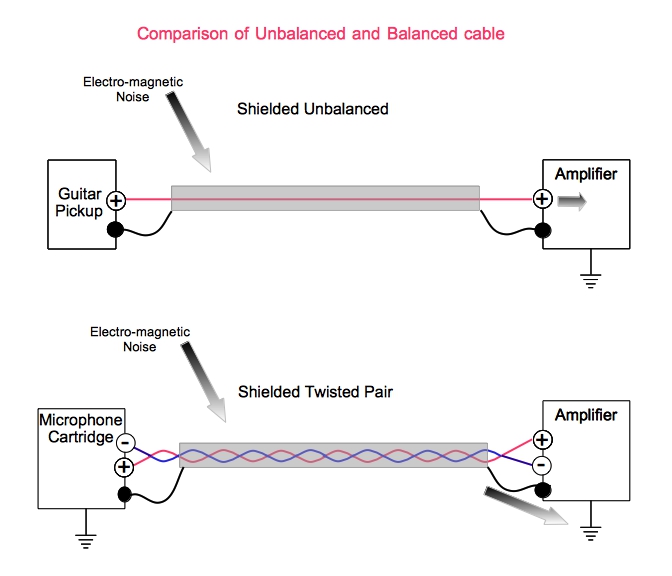
In a shielded cabled, braided or twisted wire filaments create a "shield " which surrounds the conductor(s). The unwanted current is thus imposed on the shield, then it is drained to "ground " because the shield is usually connected to ground at one end of the cable (at the chassis of a guitar amplifier, for example).
Sound installations located near radio sources often use ferrite RFI (radio frequency interference) noise filters. These are small devices which can simply be clipped around an unbalanced cable to "soak up " or "choke " the offending radio frequencies before they are transmitted to the amplifier or mixer.
A typical electric guitar amplifier circuit is unbalanced, meaning there is a common ground between the jacks and the metal chassis the circuit is built on. The audio signal is referenced to that ground. The guitar circuit is similarly referenced, and the circuit cavity is usually lined with foil, also attached to the ground (which is the "sleeve " on the plug.) As a result, electric guitar circuits tend to be susceptible to picking up radio and power frequency noise. Modern equipment has been crafted to minimize this, but only when it is used as intended. By the way, this is how the electrical system on a car is wired: the negative battery terminal (usually, nowadays) is connected the the metal chassis of the car, so to light a bulb at the back of the car, you only need to run one wire; you connect the other bulb terminal to the chassis.
This is probably a good place to talk about avoiding noise when you use an electric guitar cord. The diagram below shows an acoustic guitar connected to an amplifier directly or through a mixer channel, and a speaker driven by the power amplifier. (Some guitar rigs also use a pre-amplifier to boost the signal and "fatten" the sound.)
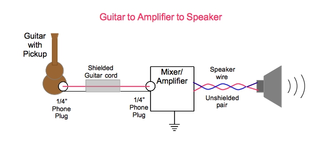
The design of the phone plug means that the tip is the part most sensitive to picking up noise. When you unplug the cord from the jack in the amplifier, the tip is disconnected from the amplification circuit first. This is a quiet disconnection. You can then disconnect the guitar end of the cord without making noise. If you reverse that sequence, and unplug the guitar end first, the tip will touch the grounded elements of the guitar as it is withdrawn, which is mostly anything metallic. The guitar then transmits stray voltage (picked up from the air) directly to the amplifying circuit, which makes it louder and sends it out of the speaker, generally as a very disruptive noise.
So the polite (and non-destructive) way to disconnect a guitar cord is to remove the far end first from whatever it is plugged into (direct box, effects box, sound system snake, mixer channel, or amplifier input). Then the near end plugged into guitar, keyboard, or other sound-producing device can be quietly removed. Alternatively, you can accomplish the same thing by turning down the amplifier volume, or muting the mixer channel it is plugged into, if either of those is an option. Just remember: in this particular case, the easiest thing to do (just yanking the cord out of your guitar first) is the wrong thing to do. Conversely, if you plug the far end into a live input before you connect the guitar end, the tip will pick AC voltage, which will introduce an annoying hum into the amplification system. Frankly, it's a hard lesson to learn, and easy to forget. (A direct box connection confused me just a few weeks ago.) So it will happen. But at least now you know why it happens and how to avoid it.
Now back to the topic at hand.
The typical XLR microphone input operates in balanced mode. There are three conductors: a "+ " signal conductor, a "- " signal conductor, and a grounded shield. The circuit operates on the voltage differential between the + and - wires. The balanced configuration significantly reduces the circuit's sensitivity to radio and power frequency noise. In addition, the connecting pins in an XLR are not only protected from accidental contact with metal, the ground pin is slightly longer, so it is the first element to connect, and the last element to disconnect. This, combined with the low impedance characteristics of the input circuit, means that you can unplug an XLR microphone cable without making noise.
Twisting the signal wires together is another trick discovered by telephone networking engineers. Not only does twisting them keep the wires together, making them easier to handle, it also means that the current imposed on the wires by an electromagnetic field is imposed equally in both wires. Since the amplifier is amplifying the difference between the two wires, any noise current introduced into the cable is ignored by the circuit.
Finally, here's a useful reminder from the Wikipedia article on balanced audio: Balanced connections typically use shielded twisted-pair cable and three-conductor connectors. The connectors are usually three-pin XLR or 1/4 inch (6.35 mm) TRS phone connectors. When used in this manner, each cable carries one channel, therefore stereo audio (for example) would require two of them.
The diagram below shows a symbolic rendering of the benefit of using a balanced input and twisted pair cable.
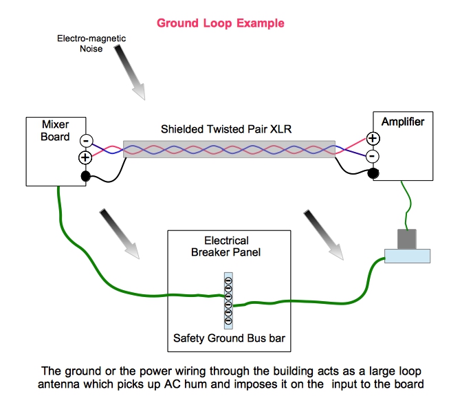
In a typical sound system the mixer is at one end of the room and the performers' amplifiers (for example) are at the other end of the room. The mixer is usually plugged or wired into an electrical outlet at the back of the room, and the amp is plugged into an electrical outlet at the front. Each individual electrical power wire is run separately back to the circuit breaker panel located elsewhere in the building. It's sort of the opposite of a twisted pair. The effect of this is to create a "ground loop", which acts as an antenna to pick up electrical noise (see diagram). Modern circuits tend to be less susceptible to ground loop noise, but it sometimes still crops up as an unexplained hum on one or more mixer channels. The ideal solution is to make sure there is a single grounding point for the complete installation, but this is not always possible. Many audio devices include a "ground lift " option to try to address this issue. Another solution is to use a ground-lift AC plug, but this is not recommended as it defeats the safety aspects of the ground wire.
As noted, many common audio terms lack a standard definition. This section addresses some of these terms, and the XLR section below provides additional insight.
This excerpt from the Wikipedia article on XLR is a concise explanation for a relatively complex topic: "The terminology for labeling the corresponding members of a pair of mating connectors follows the usual rules for the gender of connectors: a 'male' connector is the one with pins on the smallest element, 'female' has corresponding receptacles. A 'plug' connector enters the 'socket' connector, judged by the largest element. For most XLR, plugs are male and sockets are female. XLR are unusual as, at least in audio applications, all four combinations of male and female, plugs and sockets are equally common. A common misnomer is that 'plugs' are free connectors and 'sockets' are panel-mounted, but XLR uses many free female sockets and panel-mounted male plugs. There is a loose convention for audio work that signals are generated by equipment with male pins and transmitted to those with female receptacles."
| Description | Image |
|---|---|
| Banana Jacks | 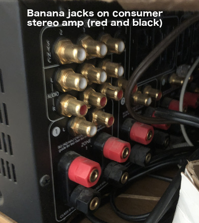 |
| Banana Plug | |
| Coax | 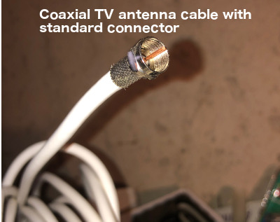 |
| Direct box | 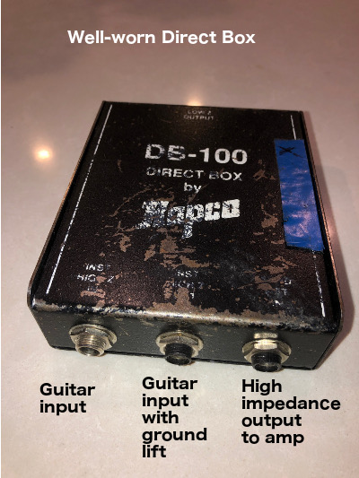 |
| Direct box - interior | 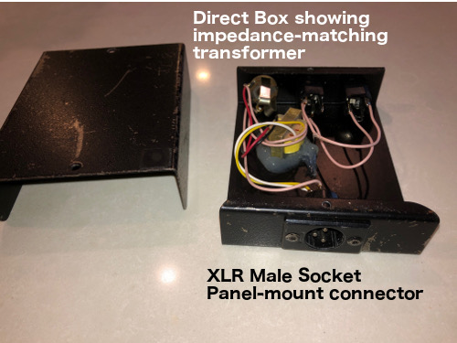 |
| Ferrite filter, clip-on | 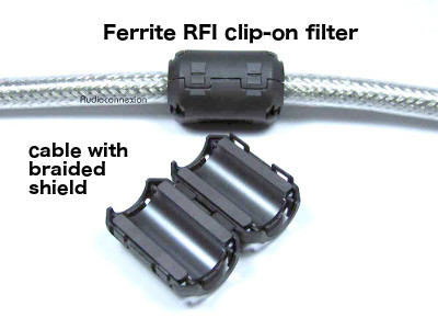 |
| Guitar cord | |
| Insert cables | |
| Mackie board | 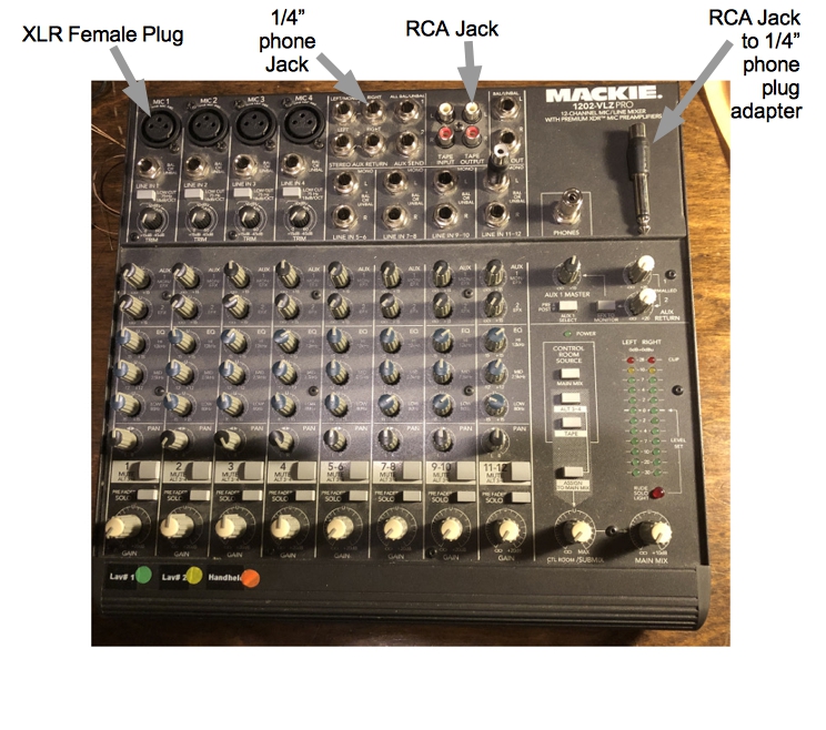 |
| Mackie board - rear panel | 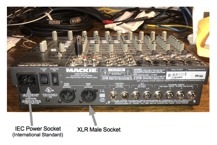 |
| Odd adapter 1 | 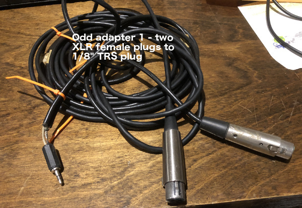 |
| Odd adapter 2a | 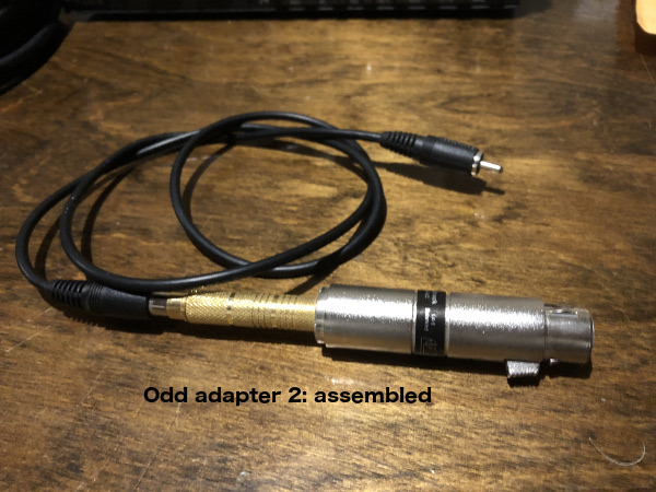 |
| Odd adapter 2b | 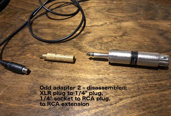 |
| Speaker clips |  |
| Speaker Twist Connector (Neutrik Speakon) - cable end | |
| Speaker Twist Connector (Neutrik Speakon) | 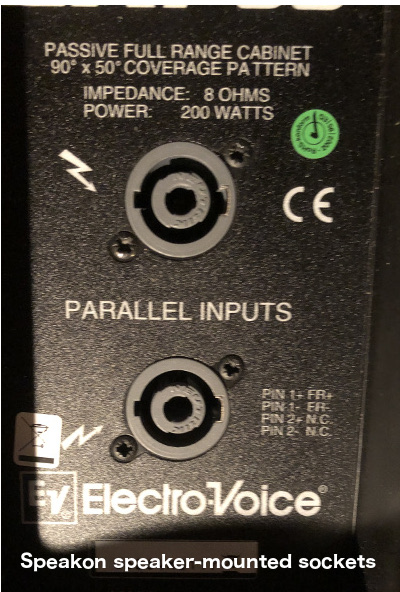 |
| Phone jack with switch | |
| Tip-Ring-Sleeve (TRS) adapters | 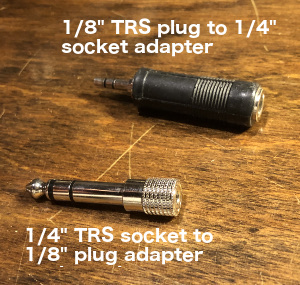 |
| TRS-RCA (Phono) stereo adapter | |
| XLR microphone cable | |